Looking great.
because wiring is not something that I knew very well, when I started working on guitars I really broke it down into tiny steps. Here are the first few I would do in your situation:
1-look at your wiring color code or use a multimeter to figure out which of the HB wires are for the coil tap. Assuming you don't need that, solder those together. I would also recommend folding them back and insulating them with heat shrink tubing.
2- scuff the backs of the pots with sandpaper, then solder lug 3 to the back of the volume pots
3- attach the tone cap according to whatever diagram you've decided on.
and so on. If you just do one step, stop, check your work, take a break- it comes together pretty fast.
Re: A Warmoth Build Thread
82Excellent. Thank you, I'll start there and see how it goes. I've got some extra pots that I'm going to practice on in the meantime.c jury wrote: Tue Aug 12, 2025 12:25 pm Looking great.
because wiring is not something that I knew very well, when I started working on guitars I really broke it down into tiny steps. Here are the first few I would do in your situation:
1-look at your wiring color code or use a multimeter to figure out which of the HB wires are for the coil tap. Assuming you don't need that, solder those together. I would also recommend folding them back and insulating them with heat shrink tubing.
2- scuff the backs of the pots with sandpaper, then solder lug 3 to the back of the volume pots
3- attach the tone cap according to whatever diagram you've decided on.
and so on. If you just do one step, stop, check your work, take a break- it comes together pretty fast.
Re: A Warmoth Build Thread
83I was looking at my LP to get an idea of what to do. The caps going from vol to tone are connecting the pots together. That's an easy one. I noticed lug 3 was bent back and soldered directly to the pot. (Would that even be necessary?) The braided cables are soldered to the volume pot bodies for ground, then its wired on to lug 1.
Then there's wires going from the switch. I saw that there was an anchor where the pot wires were soldered to one end, and the wires for the switch were soldered to the other and then a thicker wire was connected to that into the input jack. Assuming that's some kind of junction.
I didn't see where pots were grounded to the body. Is that only necessary in some cases? (like, if you don't have a wire braided with a metal shield?) There was a green wire on the opposite side of the switch that I'm guessing is ground that was also connected to the junction.
I could probably use this as a guide and then look elsewhere for treble bleed circuits.
Re: A Warmoth Build Thread
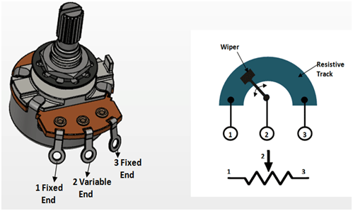
84FWIW this is the wrong convention. Solder lugs on a pot are labeled L-R when the shaft is facing you, so the grounded lug on a volume control is pin 1.
- The back of the pots are grounded, yes.cakes wrote: Tue Aug 12, 2025 2:41 pm I was looking at my LP to get an idea of what to do. The caps going from vol to tone are soldering the pots together. That's an easy one. I noticed lug 3 was bent back and soldered directly to the pot. (Would that even be necessary?) The braided cables are soldered to the volume pot bodies for ground, then its wire on to lug 1.
Then there's wires going from the switch. I saw that there was an anchor where the pot wires were soldered to one end, and the wires for the switch were soldered to the other and then a thicker wire was connected to that into the input jack. Assuming that's some kind of junction.
I didn't see where pots were grounded to the body. Is that only necessary in some cases? (like, if you don't have a wire braided with a metal shield?) There was a green wire on the opposite side of the switch that I'm guessing is ground that was also connected to the junction.
- Is it necessary to bend lug 1 to the back of the pot? No, but it does need to be connected to ground and this is the standard way that its done. There is no correct way, though.
- The braid is the cable shield and when it is grounded it shields your signal from picking up radio waves, noise, etc.
- Nothing is grounded to the body, as its non-conductive. The bridge is grounded, though, as are the strings by metal-metal connection.
For whatever reason almost ALL guitar wiring diagrams are drawn as layouts, not schematics, and I find it maddening and difficult to visualize the flow, especially for a lay person. A layout shows the parts how they visually look and are sized, like so:

But a schematic is more concerned with showing part connections and electron flow. This a schematic of a slightly different guitar, but it visually makes more sense to me:
Re: A Warmoth Build Thread
85Awesome, thanks!
For clarification, I meant that if your body cavity is shielded, that in some cases that is used for ground.
My humbucker doesn't have the standard braided shield. I have shielded the body cavity, though.
For clarification, I meant that if your body cavity is shielded, that in some cases that is used for ground.
My humbucker doesn't have the standard braided shield. I have shielded the body cavity, though.
Re: A Warmoth Build Thread
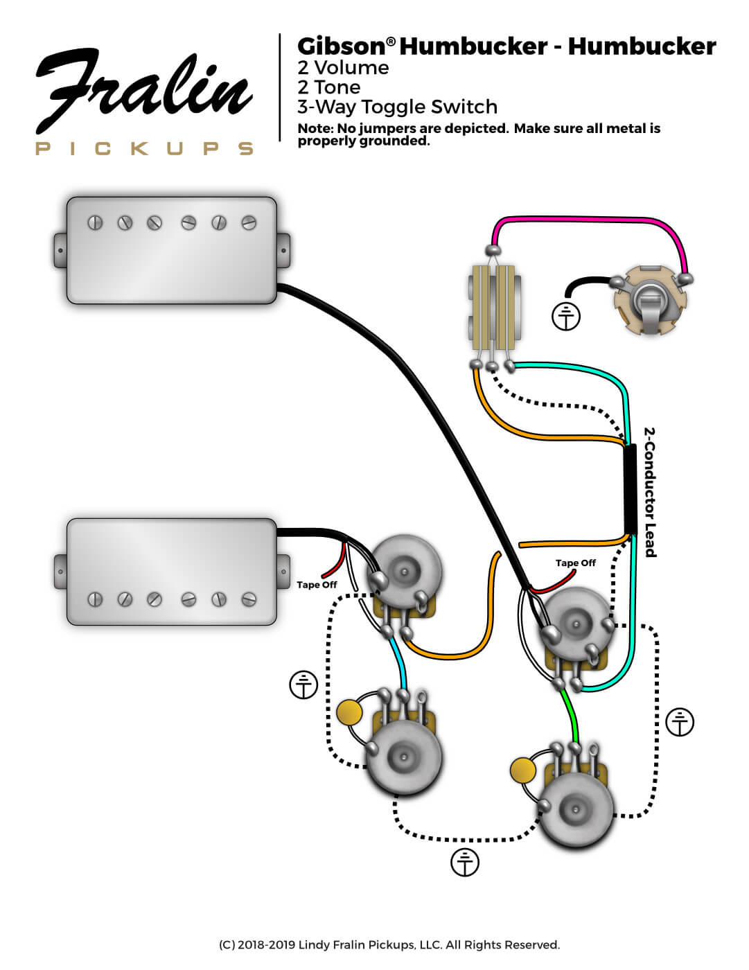
86I am going with the wiring diagram below. My neck humbucker is a 3 conductor wire, and the p90 has blue/white/black wires. I'm pretty sure the blue wire needs to be tied to the black wire and soldered together to the back of the pot and the white wire is hot. For the Humbucker, I'm not doing any split coils, so I'll just tape off the red wire with some shrink tubing.
I have a few questions, though. I've seen the ground from the switch used in two ways: a single shielded, braided wire wrapped around and soldered to each pot (which looks like what this diagram is indicating), or using the braided wire to hook up the pots to the switch, then solder a smaller piece from the ground lug to the wires connecting the pots to the switch. Any problems with that or other recommendations?
Next would be the input jack. Looks like it just needs a ground. I have foil in the guitar cavity making a faraday cage, should I solder the ground to the foil?
Re: A Warmoth Build Thread
87Here's my plan, can I get a check on my homework?
1. Create a ground bus with a braided wire between all pots, connecting to the switch ground
2. Solder the caps in parallel on lug 3 of the tone pots (as pictured in the diagram)
3. For the P90 bridge pickup, solder the blue and black wires to the vol pot together, the white wire (verified hot wire) to vol lug 3, and the vol lug 3 to the tone lug 2 with an additional wire, then solder a wire from lug 2 of the volume pot to one side of the switch
4. For the Humbucker neck pickup, solder the black and bare wires to the vol pot together, tape off the red wire and solder the white wire to vol lug 3, and the vol lug 3 to the tone lug 2 with an additional wire, then solder a wire from lug 2 of the volume pot to one side of the switch
5. Solder a wire from the switch to the input jack
6. Solder a ground wire from the input jack to a pot on the ground bus
7. Connect a ground wire from the bridge to the ground bus
Re: A Warmoth Build Thread
88I got the soldering done. Quite the shit job, honestly. I get signal just fine, but the volume pots are acting more like tone pots.
Re: A Warmoth Build Thread
89yep- the first couple are always tough. No way around it but to keep practicing.
if you post pics, we can maybe troubleshoot, or give pointers. I recognize it is probably something you'd rather not share, But no one here is gonna judge.
if you post pics, we can maybe troubleshoot, or give pointers. I recognize it is probably something you'd rather not share, But no one here is gonna judge.